ESP32-H2 with BME680 Sensor
Our mission is to foster a delightful connection between an ESP32-H2 microcontroller and a BME680 sensor, all while throwing the I2C protocol into the mix. We’re trying to make it simple by testing this communication using the i2c-tools from the ESP-IDF examples. Our assumption is that you’ve got an ESP32 development environment with ESP-IDF ready to roll, just like we spilled the beans in the ESP32 development in Docker post.
Hardware Shenanigans: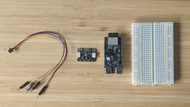
- STEMMA QT / Qwiic JST SH 4-pin to Premium Male Headers Cable - 150mm Long
- Adafruit BME680 - Temperature, Humidity, Pressure and Gas Sensor - STEMMA QT
- ESP32-H2 Development Kit ESP32-H2-DevKitM-1
- 1/2 Breadboard
The Adafruit BME680 sensor is all about avoiding the soldering drama with its STEMMA QT connectors. With QT cables, we’re simply plugging the sensor into the breadboard, where the ESP32-H2 Development Kit is ready to party.
QT cable colors meaning in context of I2C are:
- Black -> GND
- Red -> V+
- Blue -> SDA
- Yellow -> SCL
ESP32-H2 default pins for I2C assigned in i2c-tools are (source):
- GPIO1 -> SDA
- GPIO2 -> SCL
- GND -> GND
- VCC -> 3.3V
We can verify GPIO default pins assigment by looking at the source code of i2c-tools:
$ grep -r -C1 "static.*gpio_sda.*1;" $IDF_PATH/examples/peripherals/i2c/i2c_tools/main
/opt/esp/idf/examples/peripherals/i2c/i2c_tools/main/cmd_i2ctools.c-#if CONFIG_IDF_TARGET_ESP32S3 || CONFIG_IDF_TARGET_ESP32H2
/opt/esp/idf/examples/peripherals/i2c/i2c_tools/main/cmd_i2ctools.c:static gpio_num_t i2c_gpio_sda = 1;
/opt/esp/idf/examples/peripherals/i2c/i2c_tools/main/cmd_i2ctools.c-static gpio_num_t i2c_gpio_scl = 2;
Let’s get this party started by pairing the male QT cable pins with the ESP32-H2 pins:
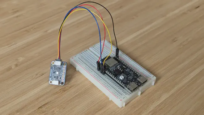
QT cable pins with ESP32-H2 pins:
- Black -> G
- Red -> 3v3
- Blue -> GPIO1
- Yello -> GPIO2
Time for ESP-IDF setup and I2C testing. Warm-up the crowd with these commands to set up the ESP-IDF environment and build the i2c-tools example
$ . $IDF_PATH/export.sh
$ cp -R $IDF_PATH/examples/peripherals/i2c/i2c_tools/ $PWD/
$ cd i2c_tools
$ idf.py set-target esp32-h2
$ idf.py build
$ idf.py -p /dev/ttyUSB flash monitor
i2c-tools command prompt welcomes us:
i2c-tools>
Now let’s try the i2cdetect command:
i2c-tools> i2cdetect
     0  1  2  3  4  5  6  7  8  9  a  b  c  d  e  f
00: -- -- -- -- -- -- -- -- E (123870) task_wdt: Task watchdog got triggered. The following tasks/users did not reset the watchdog in time:
E (123870) task_wdt:  - IDLE (CPU 0)
E (123870) task_wdt: Tasks currently running:
E (123870) task_wdt: CPU 0: console_repl
E (123870) task_wdt: Print CPU 0 (current core) backtrace
Print CPU 0 (current core) registers
Stack dump detected
Core  0 register dump:
MEPC    : 0x4201a26c  RA      : 0x4201a5d2  SP      : 0x4081b4e0  GP      : 0x4080cc70
0x4201a26c: i2c_ll_master_clr_bus at /opt/esp/idf/components/hal/esp32h2/include/hal/i2c_ll.h:749 (discriminator 1)
 (inlined by) i2c_master_clear_bus at /opt/esp/idf/components/driver/i2c/i2c.c:656 (discriminator 1)

0x4201a5d2: i2c_hw_fsm_reset at /opt/esp/idf/components/driver/i2c/i2c.c:679

TP      : 0x4080e4ac  T0      : 0x400184be  T1      : 0x00002000  T2      : 0xffffffff
0x400184be: memset in ROM

S0/FP   : 0x4080c8a0  S1      : 0x00000000  A0      : 0x00000000  A1      : 0x4081b4e8
A2      : 0x00000001  A3      : 0x00000800  A4      : 0x60004000  A5      : 0x00000377
A6      : 0x00000004  A7      : 0x00000001  S2      : 0x00000007  S3      : 0x00002e56
S4      : 0x4081a4b4  S5      : 0x00000000  S6      : 0x00000000  S7      : 0x00000000
S8      : 0x00000000  S9      : 0x00000000  S10     : 0x00000000  S11     : 0x00000000
T3      : 0x00000001  T4      : 0x40810edc  T5      : 0x00000000  T6      : 0x00000000
MSTATUS : 0x00001000  MTVEC   : 0x00000014  MCAUSE  : 0x00000052  MTVAL   : 0x0000009f
MHARTID : 0x0000004e
Let’s dive in and check if we can get some intel from the BME680. Oh, by the way, the default I2C address for BME680, according to this tutorial, is 0x77. Let’s give that a shot:
i2c-tools> i2cget -c 0x77 -r 0x00 -l 1
0x1f
- -c option to specify the address of I2C device (acquired from the tutorial, i2cdetect command failed us there).
- -r option to specify the register address you want to inspect.
- -l option to specify the length of the content.
Hooray, communication is rolling! What is 0x1f reply? How can we read more info from the BME680 sensor?
We will continue in the next post ESP32-H2 with BME680 Sensor Part 2.
References: